Particles and Procedural Effects Blog
Cooling Tower Demolition
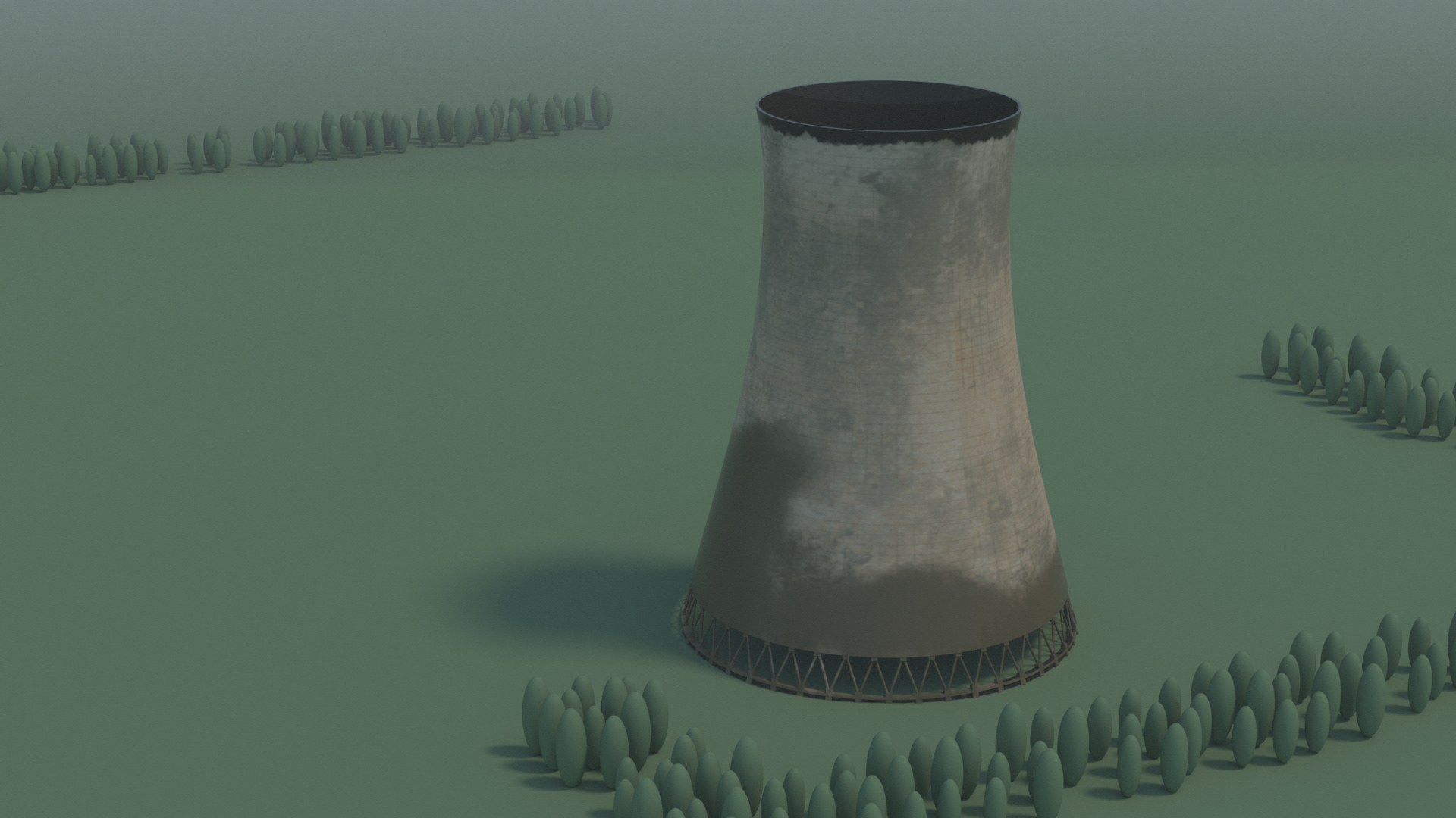
For this project, I will be working on the demolition of a cooling tower using pyro simulation, and I will be focusing on one of the cooling towers at the front. The primary goal is to simulate the smoke effects, specifically capturing the ring-shaped smoke and the smoke launch that follows after the collapse.
Render:
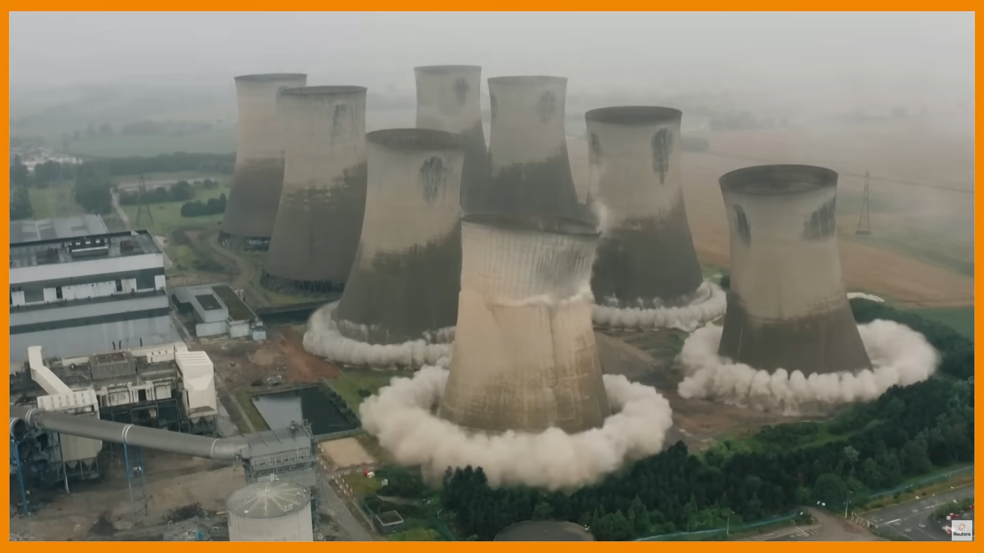
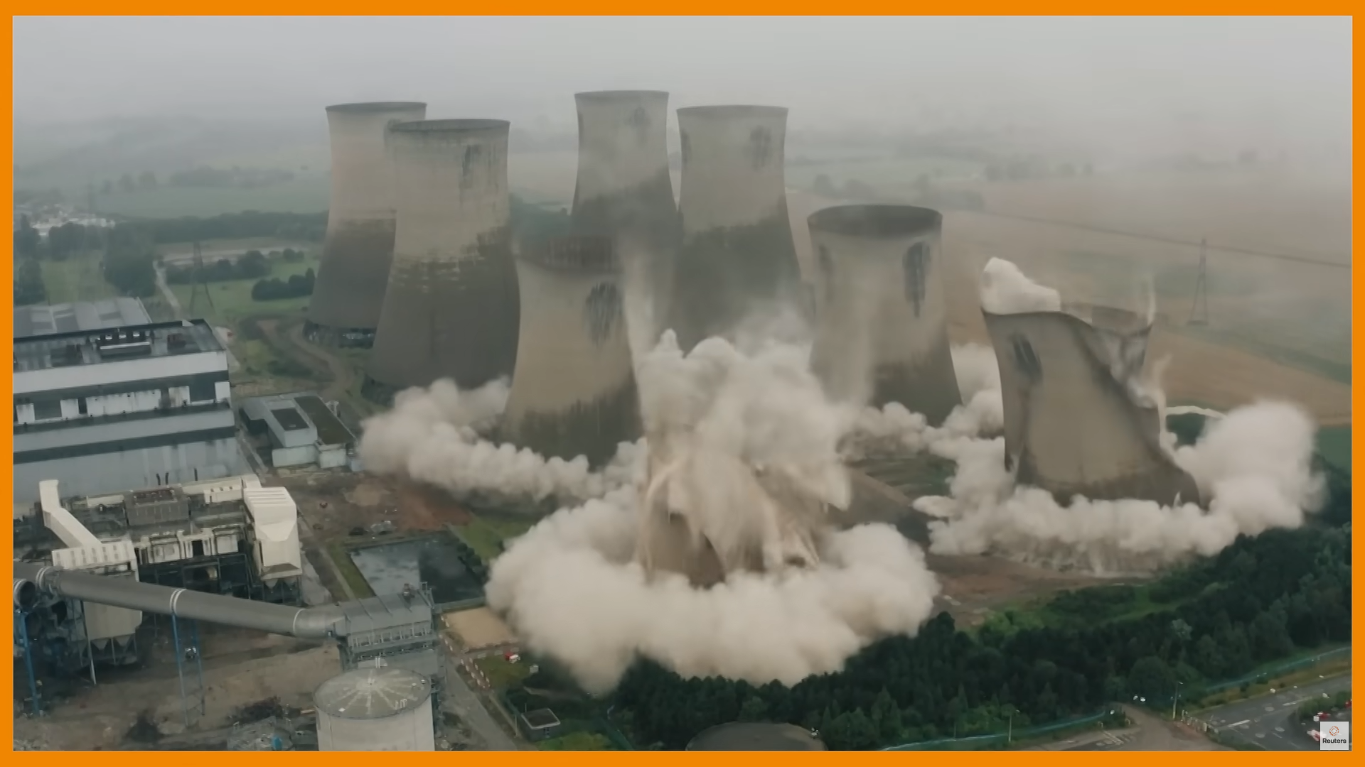
Reference:
Eggborough Power Station Demolition: https://www.youtube.com/watch?v=d77LbF6gk70
Breakdown:
05/26/2025 - Update 06
Render Image:
Flipbook:
Updated Flame Simulation:
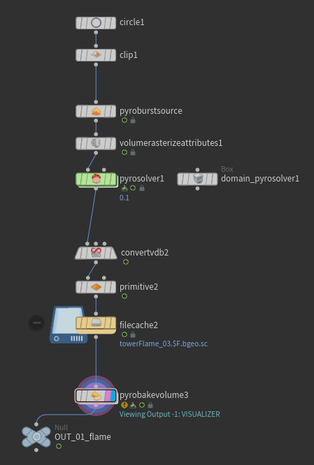
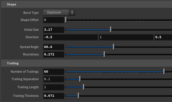
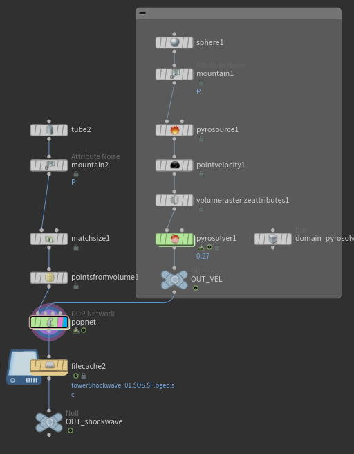
Fig. 13 | Pyro Burst Source
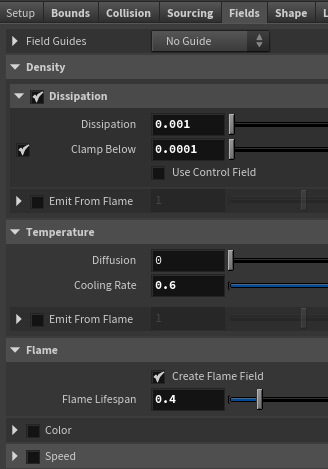
Fig. 14.1 | Pyro Solver
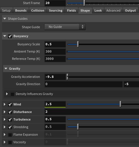
Fig. 14.2 | Pyro Solver
The shape of the flame is controlled through the fire burst source (see Figure 13. Figure 14 shows the setting of the pyro solver. The main thing I changed was the dissipation that controls how long the smoke will last during the simulation, and adjusted the shape of the smoke under the Shape tab.
Updated Shockwave Simulation:
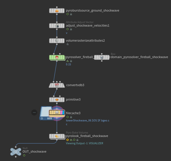
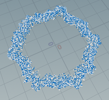
Fig. 15.1 | Shockwave Shape
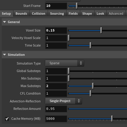
Fig. 15.2 | Shockwave Shape
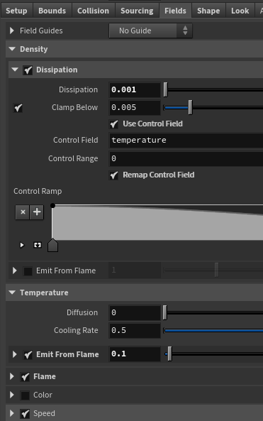
Fig. 16.1 | Smoke Shape
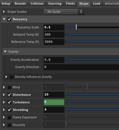
Fig. 16.2 | Smoke Shape
This is the shockwave simulation, and it has a similar setup as the flame simulation. For the pyro burst source, I used the shockwave type and adjusted the shape. I also added the shape noise to create the variation of shape. The shape of the smoke was controlled through the pyro solver (see Figure 15). Additionally, the shape of the smoke was controlled through the pyro solver (see Figure 16). To simulate the smoke behavior in the video, I made the shockwave smoke last longer by lowering the value of the dissipation.
05/20/2025 - Update 05
To Do:
- Render test frame
- Adjust the shape of the shockwave to break uniformed shape
- Adjust the density of the shockwave
- Flame at the beginning
Flame:
This is the flame test simulation.
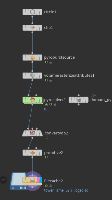
Fig. 10 | Flame
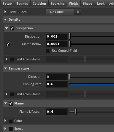
Fig. 11 | Pyro Solver Fields
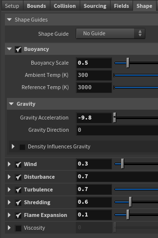
Fig. 12 | Pyro Solver Shape
Because the cooling tower demolition is the planned implosion, I used the circle and clip node to create a uniformed point position for multiple flames in the beginning. The shape of the flame is controlled through the fire brust source, and the start frame of the flame can be also adjusted in this node (see Figure 7).
In the pyro source solver, the dissipation is set to 0.001 to make the smoke last longer, and the flame lifespan was adjusted to change the timing of the flame (see Figure 8).
The convert to vdb and primitive nodes help reduce the size of the smoke simulation, and the smoke from the flame will be later combined with the shockwave smoke.
I've been trying to break the uniform shape of the shockwave, but I am having trouble adjusting the shape. I have tried to adjust the shape of the object, shape in the pyro solver, but they seem to be not changing. I'm planning to work more on this shockwave.
Render Test Frame:
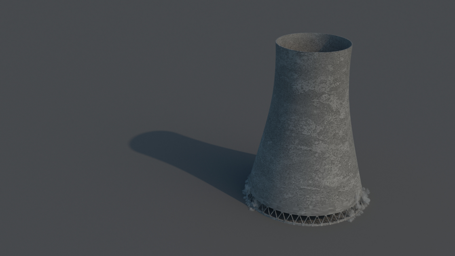
This is a render test frame to see if the texture and the simulation render correctly in Karma. If there's a time, I want to create a material from the Substance Painter, so I created a quick texture map in Substance Painter and applied it to the cooling tower.
05/17/2025 - Update 04
To Do:
- Update modeling of cooling tower
- Experiment with shockwave
Updated Cooling Tower Modeling:

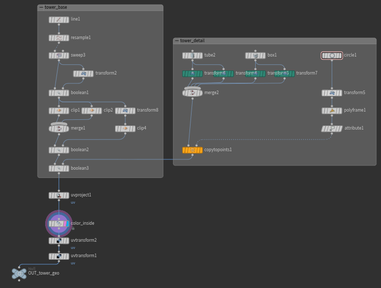
On the base of the cooling tower modeling, I used the clip nodes to create the space for the columns. The columns were created using the copy to points. The uv of the tower was separated using the binsidea from the boolean to apply different shaders for inside and outside.
Shockwave:
This is the shockwave test simulation using pyro solver.
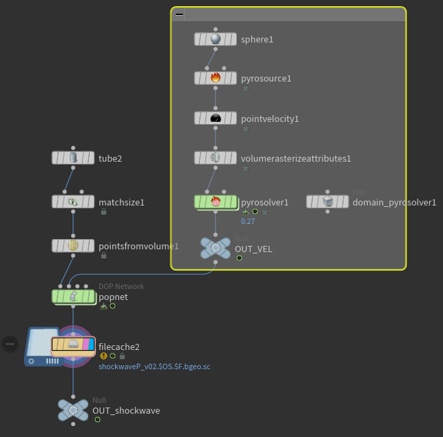
Fig. 7 | Shockwave
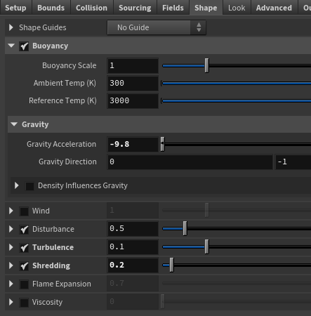
Fig. 8 | Pyro Solver Shape
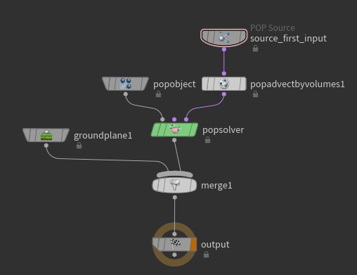
Fig. 9 | Shockwave Popnet
For the velocity of the shockwave, the sphere with the point velocity was added to create a downward force (see Figure 7). In the pyro solver, the buoyancy with the gravity acceleration of -9.8 creates the shockwave motion, and the disturbance, turbulence, and shredding was added to create variation in the smoke (see Figure 8).
The tube with the point from volume was used as the density of the points, and it was plugged into the popnet as the POP source in Figure 9. The velocity from the sphere was added as the pop advect by volumes through the second context geometry.
05/11/2025 - Update 03
To Do:
- Create debris simulation
- Smoke simulation using debris
Smoke using Debris:
Fig. 5 | Points from Debris
Fig. 6 | Smoke using Debris
After the RBD destruction, debris simulation was used to create the points from the fracture (see Figure 5). Those points were then used to create the smoke along with the Billowy Smoke.
I am planning to adjust the smoke to be affected by the gravity.
05/09/2025 - Update 02
To Do:
- Modeling cooling tower (will be updated later)
- RBD destruction using fracture
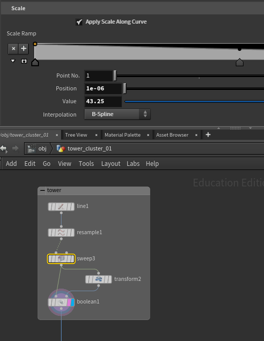
Cooling Tower Modeling:
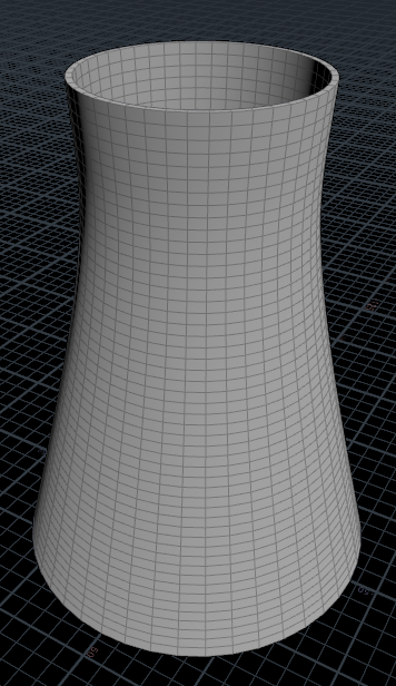
For the scale of the cooling tower, I am referencing the cooling tower from the Eggborough Power Station, North Yorkshire. Each cooling tower is 114m tall and 86.5m diameter at the base.
The height is controlled by the line node, and the radius of the base and the shape of the cooling tower is controlled by the sweep node. The boolean node was used to create thickness.
I will be adding more detail on the cooling tower later.
RBD Destruction:
This is the rbd test simulation for the first destruction.
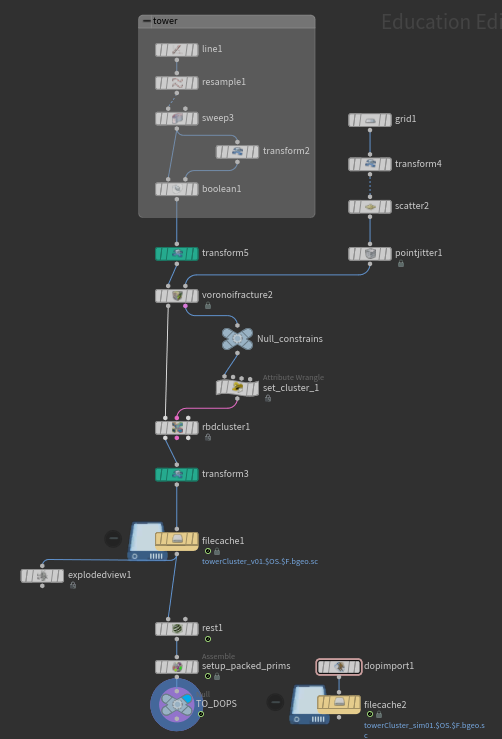
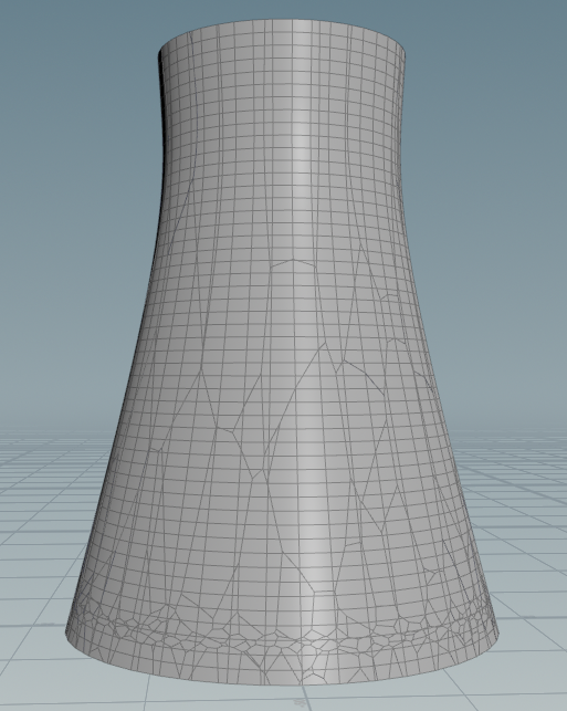
Fig. 1 | Voronoi Fracture
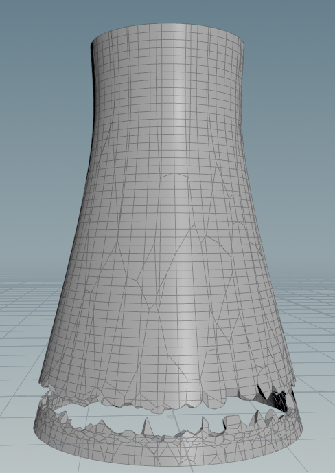
Fig. 2 | Voronoi Fracture Constraints
For the fracture, the grid with the point jitter was used to create the fracture points along the line (see Figure 1). The transform node (colored in green) was added before the voronoi fracture to scale the fracture shape by y axis, creating less division of fracture at the top. The scale of the tower was converted back to the original scale by inverting the transformation.
For the constraints, the RBD cluster node was used with the attribute wrangle to create the cluster of the fractures. In the Attribute Wrangle, the constraints were grouped and set for the cluster (see Figure 2).

Fig. 3 | Using Transform
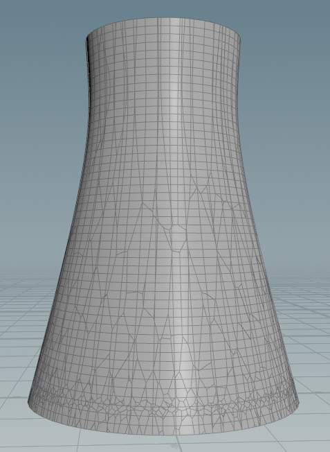
Fig. 4 | Without using Transform
Fig. 3 and Fig. 4 show the difference between using and without using the transform node before the voronoi fracture.
05/04/2025 - Update 01
For this project, I will be working on the demolition of a cooling tower using pyro simulation, and I will be focusing on one of the cooling towers at the front. The primary goal is to simulate the smoke effects, specifically capturing the ring-shaped smoke and the smoke launch that follows after the collapse.
To Do:
- Modeling cooling tower
- RBD simulation of cooling tower collapsing
- Flame at the beginning
- Smoke simulation from the flame
- RBD simulation for the fracture
- Debris simulation from the fracture
- Smoke simulation for ring shaped smoke
- Environment layout
- Render test